
As soon as I had honed in on Raspberry Pi for the codplayer platform, I planned to add an LCD display and support for a regular IR remote control. In short, make codplayer behave like a CD player. This had to wait until the player itself was complete, and progress was then awfully slow once work started. Now it’s finally deployed in my living room stereo, so let’s have a look at the construction.
Detailed build instructions and code can be found in the Github repo, currently in the lcd-ir branch but soon to be merged into master after a few more tweaks to the code.
The result
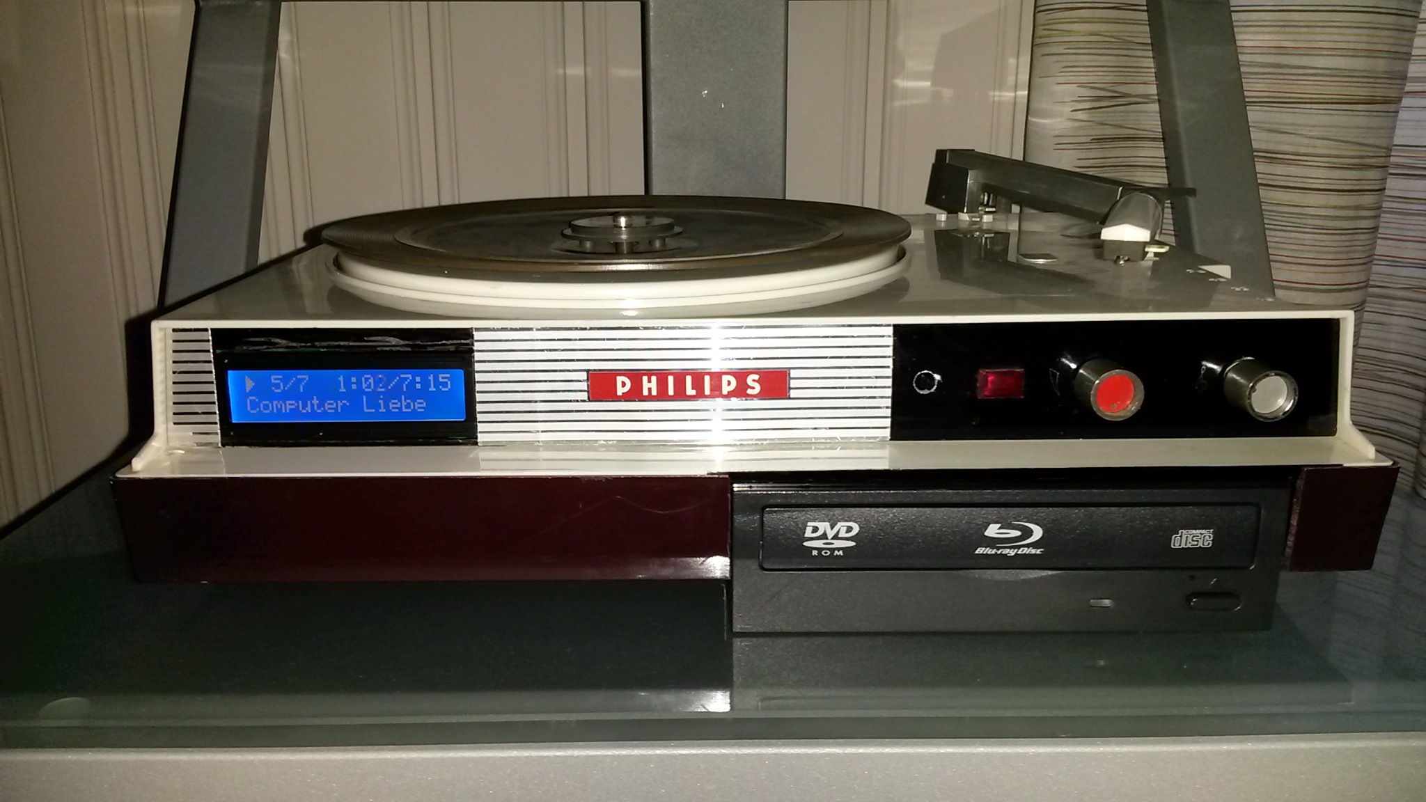
The white-on-blue LCD doesn’t suit the player, but was the only model I could get hold of easily. I plan to replace it with a red-on-black LCD later. It is controlled by the new deamon codlcd using GPIO through a Python module from AdaFruit.
The old power light is shining bright red (though barely visible in this photo), now from a LED controlled by codlcd flipping a GPIO pin. It blinks in different patterns to indicate working or error statuses, but a solid red means everything is fine.
The old tone control knob controls the LCD contrast. The volume knob doesn’t do anything yet. I’ve considered using it to control the brightness of the LCD, but haven’t yet decided if that’s better than using the remote. Currently, the remote can turn off the LCD to get rid of the glare. (This is a feature borrowed from Cyrus CD players. My amp is a Cyrus 7, so the remote has a light toggle button which codlcd listens to.) This can be extended to instead cycle through different brightness levels from 0 to 1, using PWM to control the LCD backlight.
Button presses are recieved by the IR sensor, which is connected directly to another GPIO pin where a kernel driver and lircd translates them into events that codlircd retransmits as ZeroMQ messages. Right now codplayerd only reacts to simple button presses for pause, next, previous etc, but adding support for choosing tracks by entering their number is next on the list.
The LED blinks when buttons are pressed. The simple way to do this would probably be to wire it up to the IR sensor, but I’m a programmer, not an electronics hacker. So the process is thus:
-
IR sensor transmits the recieved button signal to the GPIO pin
-
Kernel driver parses the pulses and sends the resulting code to lircd
-
lircd translates the code to a button name and publishes it on a Unix socket
-
codlircd reads the button event from the socket and publishes it as a ZeroMQ message
-
codlcd subscribes to ZeroMQ button message and blinks the LED by toggling its GPIO pin
The benefit of this roundabout way is that if the LED blinks, I know that the system actually did process the button. Right now it seems to only catch every other button press, so that is actually a useful feedback. I’m going to look at the reference wiring in the IR sensor product sheet to see if using that rather than just plugging straight into the GPIO pin improves matters. Some day. Right now I’ve had enough soldering for a while.
Building it
Once, though a combination of naivity and clumsiness, I coated an wall socket with a thin film of vapourised solder. Despite that, I managed to build this without any particular mishaps.
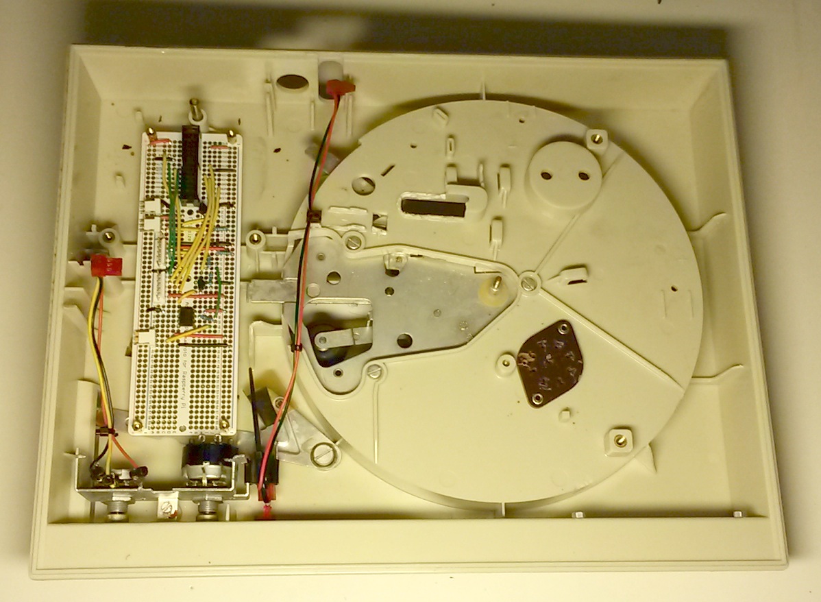
The first step was to experiment on a breadboard, using a second raspie (and at this point, a previously bought and much too big LCD):
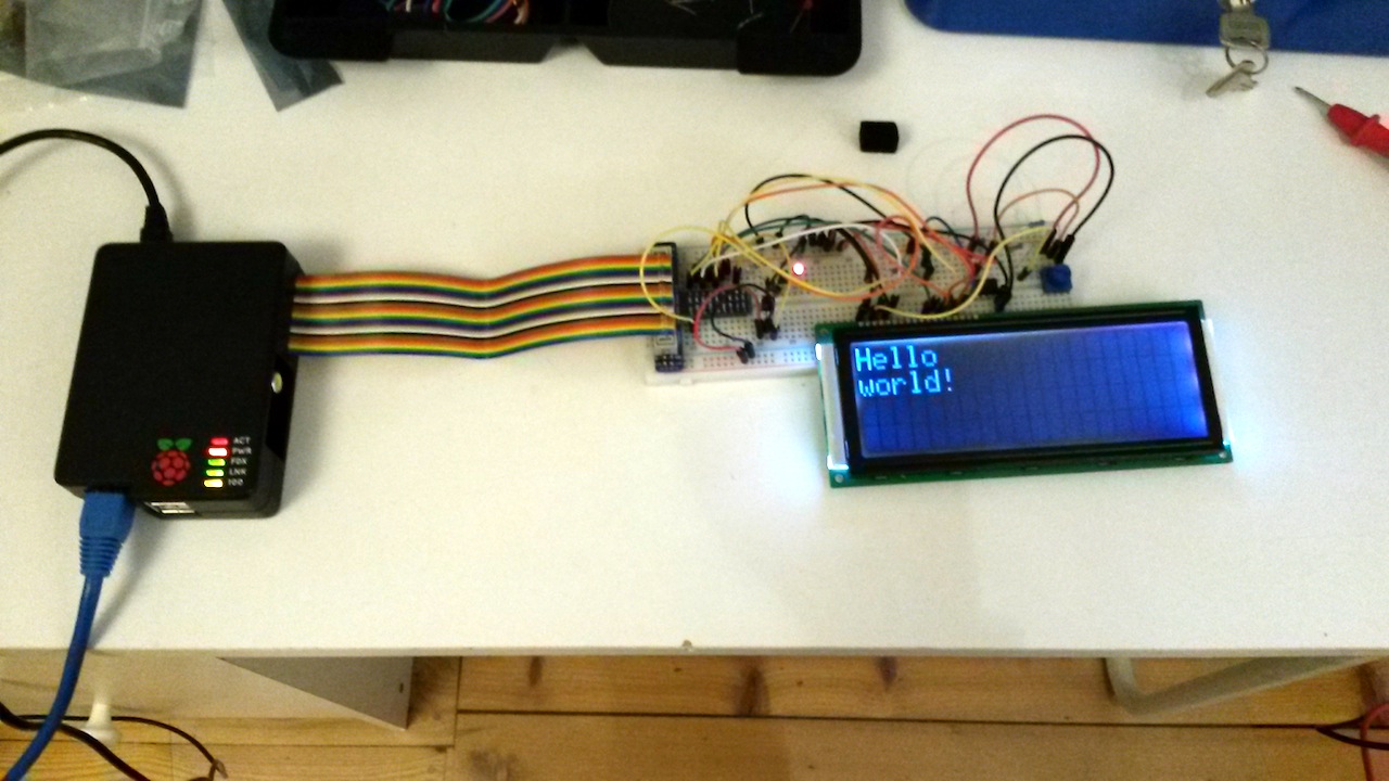
This was very useful, as I found out that the contrast control wouldn’t work very well by just hooking it up to the old tuning knob trim pot. The practical voltage range is about 0-1.5V, not the full 0-5V. A simple voltage splitter wouldn’t do the trick either, since an internal resistor in the LCD on the contrast pin turned the circuit into a resistor grid that just made everything worse. A friend suggested using an opamp in a voltage following configuration to isolate the trimpot from the resistor in the LCD. (Thanks, Wingel!)
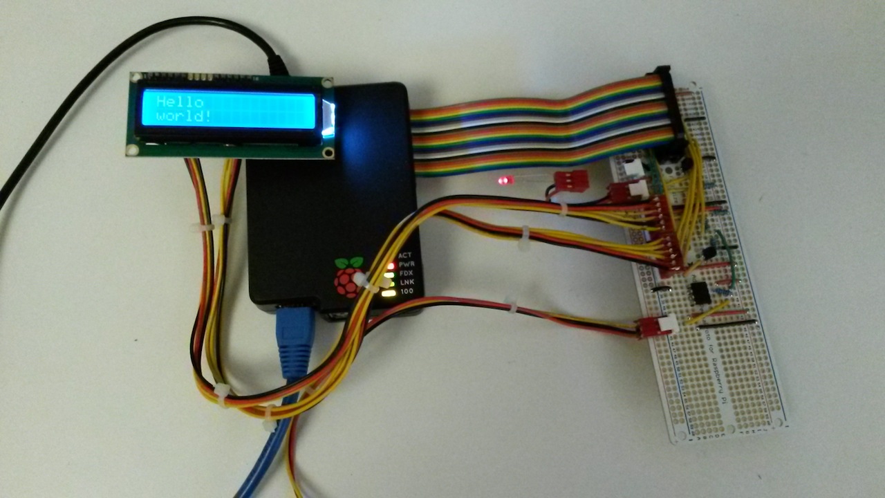
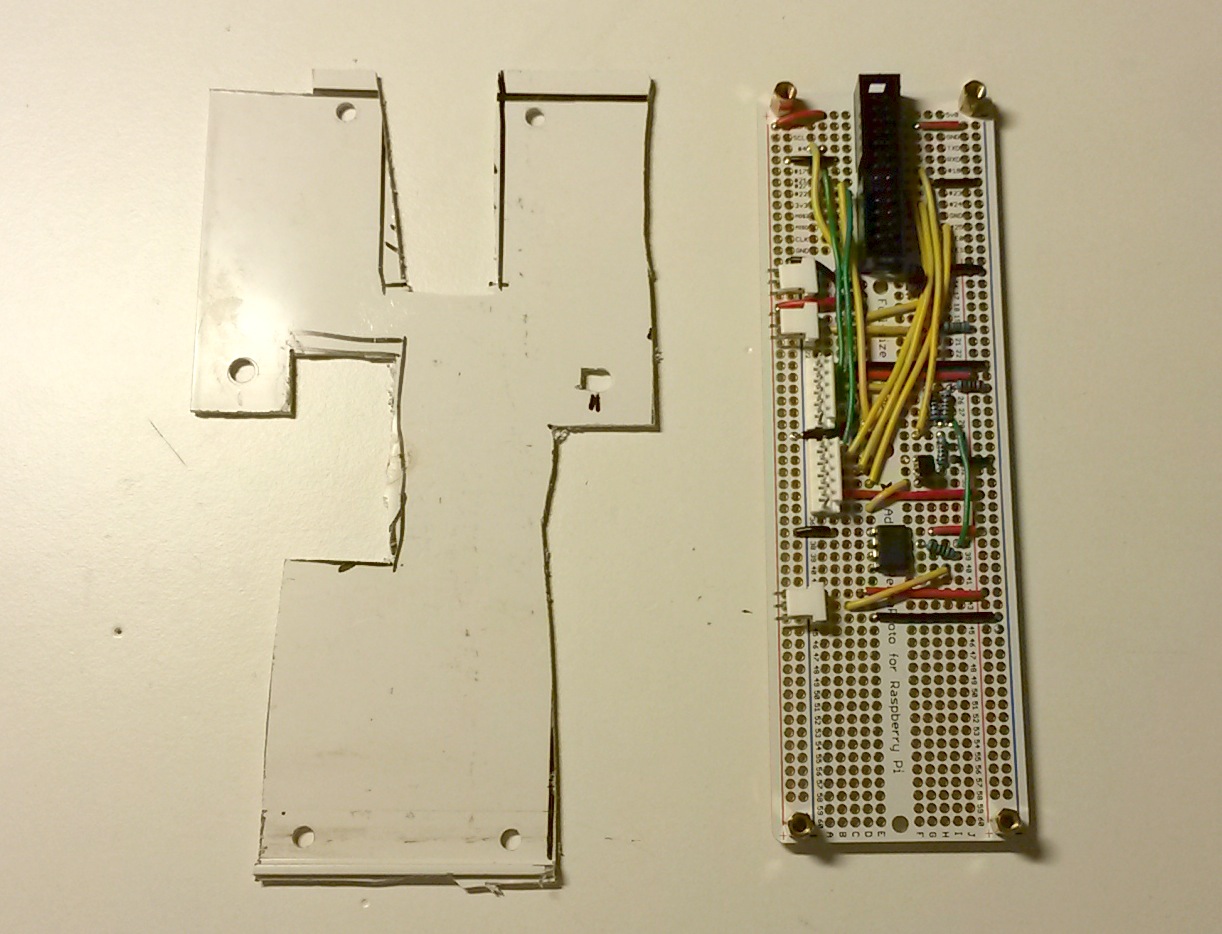
Once things seemed to work, I translated it into a circuit layout for an AdaFruit perma-proto board. It was not particularly fun wiring this up. If I did this again, I would rather put the time into learning Eagle CAD and getting a proper PCB produced. But hey, it works:
At this point the hardware hacking was replaced by coding to build the codlircd and codlcd daemons to make use of the electronics.
Next, some physical hacking with a drill, saw and blunt tools:
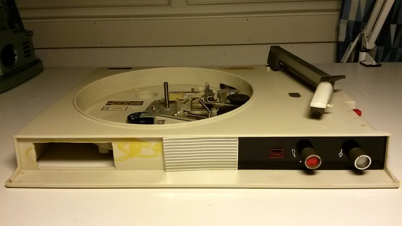
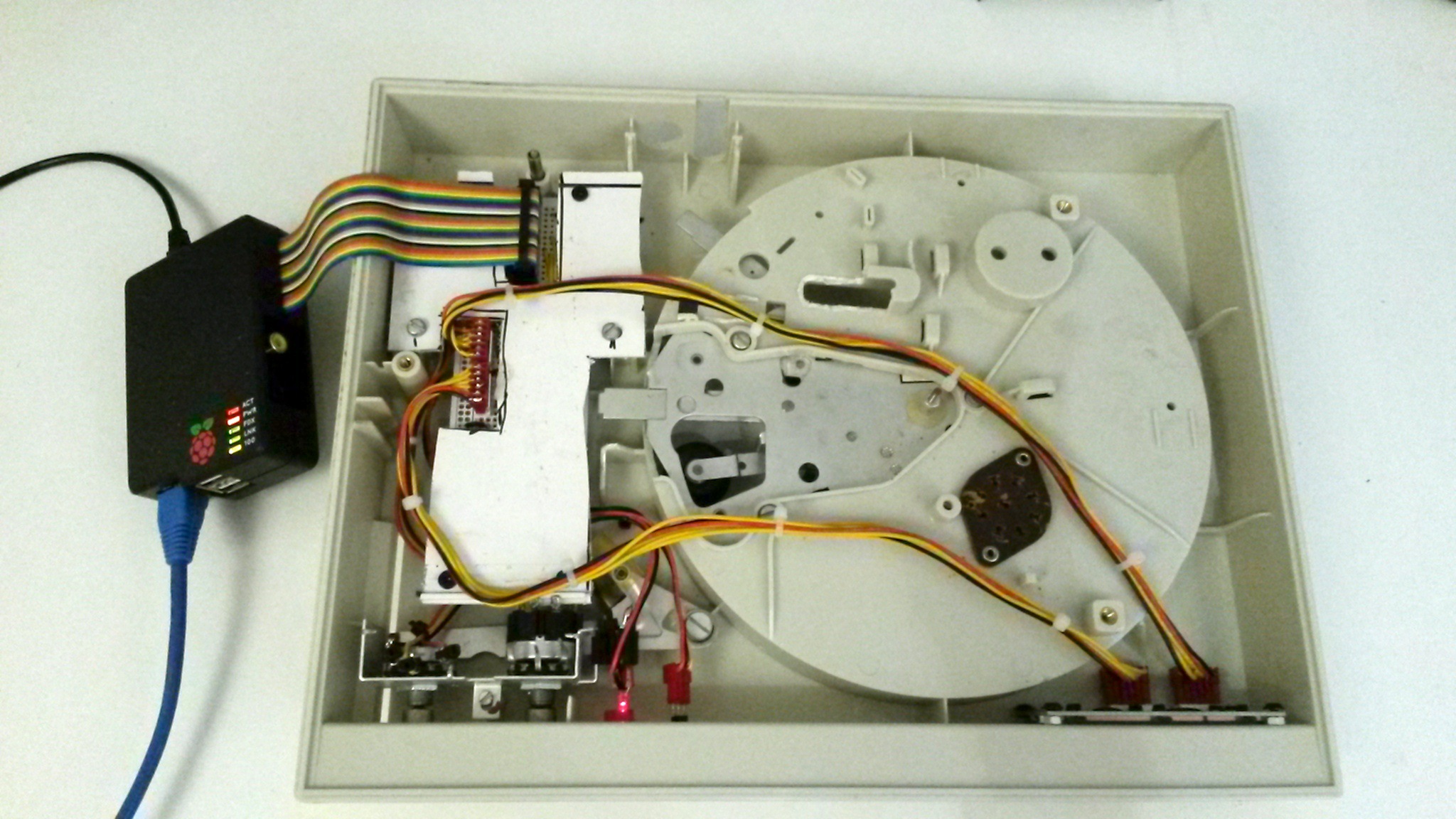
After a little bit more violence the board fit precisely into the area where the old record player circuit board and transformer once sat:
Something was needed to hold the board in place. A crudely cut piece of plastic created a holder and lid for the board, protecting it from getting into contact with the Blu-Ray reader below it:
The old screw holes that held the transformer could be reused, even the screws themselves. As a further bonus, some of the nuts once holding the record engine engine in place now provides support for the LCD. Here’s everything wired up and being tested with the second raspie:
The final step, completed today, was to cut up the old metal front to make it fit around the LCD, glue it in place and polish everything. The final results was shown at the top of the post.
 Atom feed